Moulding processes
Injection moulding
The raw material called "masterbatch" is mixed with cross-linking agents, accelerators and activators if required between two mixing rollers. After multiple passes, the material is homogenised, calibrated in thickness and cut into strips.
The masterbatch consists of an elastomer base with added plasticizer and carbon black (or mineral filler, usually used for coloured mixtures). The semi-finished material thus acquires its processing and hardness properties. Before moulding, cross-linking agents, accelerators and activators must be added to the masterbatch.
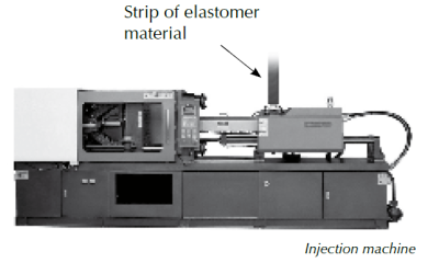
A strip of raw elastomer material is inserted into a housing and pulled by a worm screw. The material liquefies under the temperature. It is then injected under pressure into channels that fill the cavities of the tooling and the vulcanisation process begins.
The vulcanisation (or cross-linking) of an elastomer is the initiation of chemical reactions during which the monomer bases bond and form a cross-linked chain. The result is a cluster with the moulded parts and supply channels. In the finishing process, the seals are unhooked and deburred.
The cavities of the injection tool are supplied with material by means of secondary channels via a gate or injection zone. These channels are connected to the main supply channel which is connected to the injection nozzle of the press.
These tools are usually equipped with a temperature control system to maintain a homogeneous temperature inside the cavities.
The injection point (or zone) can leave a protrusion or a hollow of varying size depending on the size of the part. The maximum values of the injection points (or zones) comply with the ISO norm 3601-3:2005-N.
Tolerances on finished parts comply to the ISO norm 3302-2.
Compression moulding
The steps regarding the masterbatch are the same as for injection moulding (see above).
The elastomer sheets are cut into calibrated strips. A 100 % control of the weight of each strip guarantees that the operator has the exact quantity of material.
Using a special tool, the operator places the strips in the open compression tool. The tool closes and the vulcanisation process begins.
Vulcanisation (or cross-linking) is the initiation of chemical reactions during which the monomer bases bond and form a cross-linked chain. The result is a web of parts and the membrane that connects the final parts (commonly called "flash"). In the finishing process, the seals are "deflashed" and deburred.
Compression tools are mainly composed of two plates (one upper and one lower plate). The cavities are machined without supply channels in order to optimise the number of cavities.
The temperature of the moulds is regulated by means of electrical resistors placed in contact with the plates. Due to the simplicity of the design, the tool acquires rapidly an homogeneous temperature.
The mould is positioned horizontally (vertical opening). Its closing precision is excellent: There are few defects in the parting line due to misalignment of the plates. To produce complex shapes, theoretically unmouldable, Techné proposes a multi-plate tool concept.
Tolerances on finished parts comply to the ISO norm 3302-1.
Transfer moulding
This process uses presses similar to those used for the compression process. Transfer moulding is generally chosen for the manufacture of seals with elastomer rubber bonded or overmoulded to metal inserts.
A three-plate tool (a bottom plate, a perforated intermediate plate and a top plate) is created. The cavities are machined in the middle and bottom plates.
The inserts are placed on the bottom plate. The intermediate plate is placed on top of the lower plate. The material strips are placed on the intermediate plate, above the holes that act as injection channels. The top plate closes the assembly.
Under the effect of the closing pressure of the tool and the temperature, the material liquefies, passes through the holes and fills the cavities.
Tolerances on finished parts comply to the ISO norm 3302-2.

Moulding tolerances
All Techné moulding parts are produced according to ISO 3302-2. Depending on the process, feasibility and customer requirements, an M1 (precision part) or M2 (standard tolerances) grade will be obtained. On request smaller tolerances can be offered.
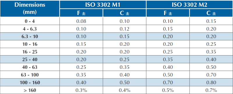
C: dimensions affected by the mold closure
F: fixed dimensions
Deburring processes
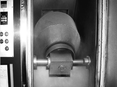
The seals in the form of clusters or sheets are placed in a rotating sieve with polymer balls or grains which is rotated and the temperature decreases from -50 °C to -70 °C depending on the material. The balls and grains projected onto the seals break the walls of the sheets or the channels of the clusters. The parts are thus separated from their bonds. The cryogenic deburring is usually completed by tribofinishing.
For a manual deburring, specific tools are used. When designing the mould, rubber cutters are provided at the periphery of the cavities. During the deburring process, the operator exerts a pulling force on this rubber cutter. The forces are then transferred to a brittle line, thus detaching the part from its web.
In some cases, Techné performs automatic deburring by cutting, commonly called "trimming". This process, which is especially valid for « revolution » parts, consists of rotating the part and using a knife to cut out an area in order to obtain a sharp angle.
The deburred part is then completely free of residual burrs. This method is often used in the manufacture of sealing rings.
Cutting processes
For the manufacture of flat gaskets, Techné and its subsidiary company Chromex use an automatic cutting process on elastomer plates.
Flat gaskets are widely used in static seals. There are two different processes: blade cutting and press cutting.
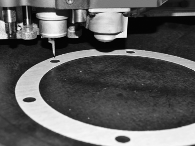
Blade cutting
The material is placed on the cutting table. It is held there by a suction system that presses it onto the table. The material is either in roll form or in sheet form. The maximum thickness that can be cut with a blade is 15 mm. The dimensions of the cutting table are 1,500 x 3,000 mm.
By executing the machine program, created using a .dxf drawing, the 2-axis cutting head supporting the blade moves over the table and cuts the elastomer. To optimise the offcut rate, the parts are cut by the help of an optical placement software.
This type of cutting is suitable for seals produced individually, in small and medium series, without additional tooling costs.
The tolerances of the finished parts are +/- 0.2 mm.
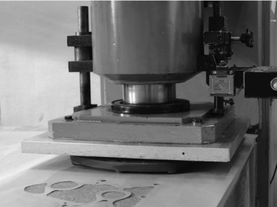
Press cutting
The material is placed on the cutting table in the form of sheets or rolls.
The press is equipped with a die-cutting tool, specifically designed according to the 2D profile. The press piston descends and the tool separates the part from the elastomer plate.
The press cutting process is particularly suitable for medium and large series.
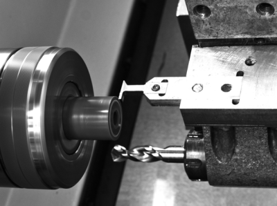
CNC machining process
The elastomer rubber material is stored as jets or bars in an automatic, air-conditioned storage tower. It has been cross-linked to a hardness of 83 +/-5 IRHD.
Techné keeps a large number of jets of different diameters in stock in order to offer short delivery times. The use of the jet that is dimensionally closest to the finished part optimises production costs and reduces the environmental impact.
The jet is placed in the spindle of the machining lathe and specific tools, adapted to elastomers, machine the required shape.
This process is reserved for circumferential seals. It is used for the manufacture of single parts, small series and maintenance seals according to a sample.
The machining of elastomer offers flexibility and speed for the production of prototypes for technical developments.
Techné also offers soft materials in 73 IRHD: NBR seals, FKM seals, HNBR seals and EPDM seals. The Techné engineering office is at your disposal for more information.
The Techné cataologue for CNC machined parts is available for download below:
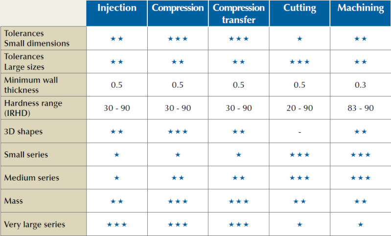
Comparison of processes